On a 1440x1080 near-eye module the interface is settled by arithmetic before it is settled by preference: the raw pixel payload for full-motion video lands in the gigabit-per-second range, which takes SPI out of the video path and puts single-ended parallel buses under pressure. MIPI DSI is the interface specified on this 0.40-inch module, and it is the expected answer at this resolution, but it relocates the work rather than deleting it, because the host now needs a DSI controller, correct lane and clock configuration, and a power sequence that survives cold boot. The practical method is to work backwards from payload, cable length and the host you already have, then treat the remaining buses as fallbacks for configuration, still images or lower-resolution panels. Inside a camera electronic viewfinder those constraints bite harder than they do on a desk monitor, because the flex is folded into a small housing and the user notices latency immediately.
Key takeaways
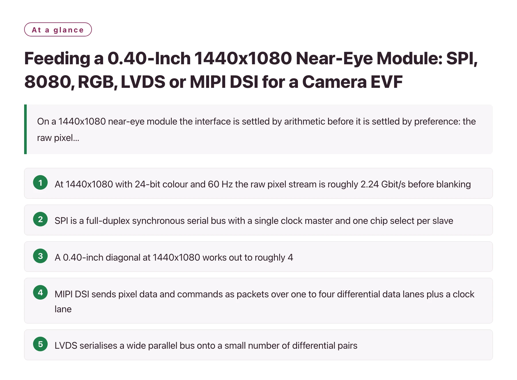
- At 1440x1080 with 24-bit colour and 60 Hz the raw pixel stream is roughly 2.24 Gbit/s before blanking, a figure no serial peripheral bus can approach.
- SPI is a full-duplex synchronous serial bus with a single clock master and one chip select per slave, which makes it ideal for register writes and still frames and unsuitable for live video at this pixel count. [1]
- A 0.40-inch diagonal at 1440x1080 works out to roughly 4,500 pixels per inch, a pixel density that only a magnified virtual image makes usable. [2]
- MIPI DSI sends pixel data and commands as packets over one to four differential data lanes plus a clock lane, which shrinks the connector to a few pins while keeping the payload in the gigabit range. [3]
- LVDS serialises a wide parallel bus onto a small number of differential pairs, which is valuable over long cable runs but adds a serializer and a wider connector next to a native DSI link.
An electronic viewfinder is a near-eye product with a hard latency budget: the image has to reach the eye close enough behind the sensor readout that the photographer does not feel disconnected from the scene. A 0.40-inch module at 1440x1080 packs roughly 4,500 pixels per inch, which is what makes a magnified virtual image look continuous rather than pixelated, and it is also why every interface option is judged by whether it can move that many pixels on time.
The module described here is specified with a MIPI interface, a 30-degree field of view and 90 percent DCI-P3 colour coverage, and it is positioned for AR/VR glasses and head-mounted displays. Those numbers describe the optical result; they say nothing about how the host will feed the panel. That gap is where most integration problems live, and it is usually discovered late, after the flex and the housing are already designed.
The rest of this article works through the five interfaces engineers normally consider for a module of this class, namely SPI, MCU-8080, parallel RGB, LVDS and MIPI DSI, using the actual pixel count and the viewfinder use case as the filter. It closes with the bring-up order that surfaces a wrong interface choice while the fix is still a firmware change rather than a mechanical one.
Start with the payload, not with the bus you already know
Interface selection begins with a multiplication rather than a datasheet comparison. Multiply horizontal pixels by vertical pixels by bits per pixel by frames per second, then add headroom for blanking and protocol overhead. For 1440x1080 at 24 bits per pixel and 60 Hz the payload is about 2.24 Gbit/s; even at 30 Hz it stays above 1.1 Gbit/s. Those numbers describe a serial link, not a shift register.
That one estimate removes SPI from the video path. SPI is a full-duplex synchronous serial bus with a single clock master and separate chip-select lines for each slave. [1] At a 50 MHz clock the payload ceiling is 50 Mbit/s, roughly forty-five times short of what this module needs for continuous frames. SPI remains the right way to write registers, switch modes or load a still frame, and many hosts end up using it alongside the video link for exactly that reason.
A parallel bus does not escape the arithmetic either. A 24-bit RGB interface carrying 1440x1080 at 60 Hz needs a pixel clock in the region of 110 to 120 MHz once blanking is included, with twenty-four data lines switching at that rate. An 18-bit MCU-8080 style bus is cheaper in pins but its usable rate is set by the controller write cycle; with a 25 ns cycle the theoretical ceiling is about 720 Mbit/s, still well below the requirement and with almost nothing left over for command traffic.
Why the pixel count, not the diagonal, sets the boundary
Resolution is the variable that moves the line between interfaces. A small panel at 320x240 can live comfortably on SPI or an 8-bit parallel bus; a 1440x1080 panel cannot, because the payload grows with pixel count rather than with physical size. It is worth asking early whether the viewfinder truly needs the full pixel count, or whether a lower-resolution module with a comparable field of view would unlock interfaces that cost less in pins, connectors and firmware effort.
The five realistic routes into a viewfinder module
| Interface | Typical wiring | Practical payload | Fit for a 1440x1080 viewfinder |
|---|---|---|---|
| SPI | Clock, data in, data out and a chip select per device | Tens of Mbit/s at commonly used clocks | Configuration, mode switching and still frames only; not viable for live video |
| MCU-8080 parallel | 8, 9, 16 or 18 data lines plus write, read, chip select and data/command | Hundreds of Mbit/s at realistic bus timing | Possible only at reduced frame rates; pin count and update tearing are the price |
| Parallel RGB | 24 data lines plus pixel clock, HSYNC, VSYNC and data enable | Gigabit range, but spread across many single-ended lines | Workable with a short flex and a host that already exposes a parallel display port |
| LVDS | Three or four differential data pairs plus a clock pair | Gigabit range concentrated on a few pairs | Capable and robust over cable, but adds a serializer and a wider connector |
| MIPI DSI | One to four differential lanes plus a clock lane in a small connector | Gigabit range, packet based [3] | Matches the MIPI interface specified for this module and the connector budget of an EVF |
What MIPI DSI actually asks of the host
MIPI DSI is a high-speed serial display interface built on differential signalling: the host transmits pixel data and commands as packets over one to four data lanes, with a separate clock lane alongside them. [3] Because the link is packet based, the same physical connection can carry a video stream, register writes and read-back, so one interface replaces both the pixel bus and the control bus that a parallel panel would need. The module described here, the 0.40" 1440x1080 display from DisplayModule, is specified with MIPI, a 30-degree field of view and 90 percent DCI-P3 coverage, so the engineering effort shifts from choosing a bus to configuring a DSI host correctly.
Lane count is a design lever rather than a specification detail. More lanes lower the bit rate each lane must sustain for a given pixel rate and improve the timing margin across a folded flex, while fewer lanes simplify routing and reduce pin count. The real constraint is usually the host: a display controller with a fixed maximum lane rate sets the ceiling, and the lane configurations the module supports set the floor. Confirm both numbers before the board layout is frozen, because changing them later means changing the connector footprint.
Video mode and command mode behave very differently in a product. In video mode the host streams continuously and the panel must keep up; in command mode the module holds a frame buffer and refreshes itself, so the link can idle between updates. A viewfinder showing a live scene wants video mode, because the image changes constantly while the shutter is half-pressed. Command mode is what a menu overlay or a status screen wants, since it lets the link go quiet between redraws.
The number to check when comparing lane counts is not average throughput but the worst-case margin on the lane eye at the highest pixel rate you intend to use.
A bring-up order that exposes interface mistakes early
- Prove the link before the optics. Drive the module outside the housing with a test pattern and a short flex. Confirm a stable, correctly coloured image before the optical stack is fixed in place, so a failure is still a wiring question.
- Write the power and reset order down first. A large share of blank-screen faults on a serial display link come from a reset released too early or a supply that ramps after the host begins sending packets. Fix the sequence on paper and match it against the module requirements.
- Configure lanes and pixel format explicitly. Set lane count, bits per pixel and packet format in the host driver instead of trusting defaults. A mismatch often appears as an image that is shifted by a few columns or has swapped colour channels rather than as no image at all.
- Measure latency at the eye, not at the panel. Time from sensor readout to photons leaving the optics with a photodiode or a high-speed camera. The display link is only one contributor, but it is the contributor you can still change in firmware.
- Re-test with the housing warm. A link that is marginal at room temperature can fail once the module and the surrounding electronics have been running for an hour, because differential timing margins and oscillator accuracy drift as temperature changes.
Questions to settle with the module supplier before tooling
Four items belong in the first technical conversation. First, the supported MIPI lane configurations and the maximum lane rate, because those decide whether your host can drive the module natively or needs a bridge chip. Second, the flex and connector definition, including pin count, impedance targets and the cable length at which the link has been characterised. A specification that is valid on a 100 mm flying lead is not automatically valid on a flex folded through a hinge.
Third, the colour pipeline. The module is specified at 90 percent DCI-P3 coverage, and how that coverage is produced determines what the host must send: sRGB, DCI-P3 or a wider gamut, with or without an internal matrix or gamma stage. Getting this wrong yields an image that looks plausible on a bench and wrong in a graded workflow, and it is the kind of error that survives several review rounds because nothing is obviously broken.
Fourth, the optical interface. Eye relief, exit pupil and the 30-degree field of view are the numbers a mechanical engineer needs to place the optics, and they cannot be inferred from a panel outline drawing. Ask for the optical drawing and the electrical drawing as separate documents, because a single combined outline tends to hide exactly the tolerances that determine whether the product can be assembled repeatably.
Treat the interface as a system budget rather than a cable. The connector, the flex, the host port, the lane configuration and the power sequence all have to survive the same thermal and mechanical environment, and they are chosen at different points in the project. A link that is comfortable on the bench with a straight flying lead can still fail inside the housing, where the flex is folded, the ground return is longer and the module is warm.
Sources
Frequently asked questions
Can a 1440x1080 near-eye module be driven over SPI?
Not for live video. The arithmetic is unforgiving: 1440x1080 at 24 bits per pixel and 60 Hz needs roughly 2.24 Gbit/s before blanking, while a 50 MHz SPI clock tops out near 50 Mbit/s. SPI remains useful for register writes, mode changes and still-frame loads, and it is the interface most hosts keep for control alongside the video link.
Why is MIPI DSI preferred over parallel RGB for a 0.40-inch viewfinder module?
Because of connector and routing cost rather than image quality. A parallel RGB link needs roughly twenty-four data lines plus clock and synchronisation signals, all single-ended and all routed past sensitive analogue and radio circuitry in a small camera body. MIPI DSI carries the same pixels over one to four differential lanes, which reduces the connector to a handful of pins. Parallel RGB is still reasonable when the host already exposes a display port and the flex is short.
What usually causes a blank or unstable first image on a serial display link?
Power and reset sequencing is the most common cause, followed by a lane-count or pixel-format mismatch between host and module. Both faults present as an image that never appears or appears with visible corruption. Bringing the link up outside the housing on a short cable, with the sequence written down rather than improvised, separates wiring and configuration errors from the optical assembly.
Does the interface choice affect colour accuracy?
Indirectly, yes. The interface determines what the host is able to send, so if the host delivers an sRGB stream to a module whose pipeline expects a wider gamut, the 90 percent DCI-P3 coverage the module is specified for describes a signal you never actually transmit. Fix the colour format and any internal matrix stage with the supplier before writing the driver, then verify with a known test pattern rather than by eye.